CROSS-FLOW MEMBRANE FILTRATION TECHNOLOGY FOR BRINE TREATMENT
CROSS-FLOW MEMBRANE FILTRATION TECHNOLOGY FOR BRINE TREATMENT
- Detail
- Parameters
l PROCESS DESCRIPTION
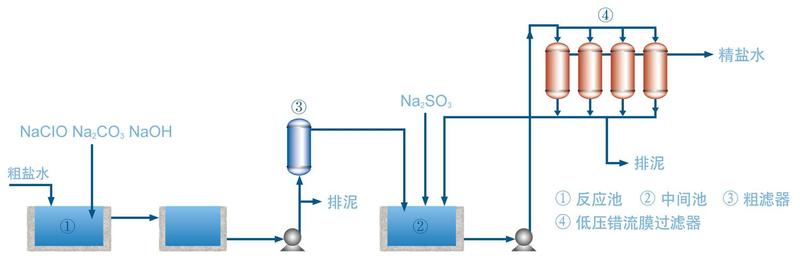
BRINE SATURATION: Dechlorinated weak brine with Sulfate Removal System incorporated for control of the sulfate level is collected and returned to the Salt Dissolver. Saturated brine from the Salt Dissolver is delivered to the Baffle Mixer where Sodium Hypochlorite, Sodium Carbonate and Ferric Chloride are added prior to the Reaction Tanks. The pre-treated brine is delivered to a second Reaction Tank where Sodium Hydroxide is added to precipitate the magnesium. The treated brine is then delivered to the Membrane Filtration Units.
BRINE FILTRATION: Treated brine is first delivered to a Primary Filter to remove particles of more than 1 micron, and subsequently delivered to the SF Membrane Filtration Unit. The filtered brine discharges from the Membrane Filter, small amount of sodium Sulfite is added to remove any residual free chlorine before sending to the Brine Ion Exchangers system. The solid particles in the brine are retained on the surface of the membrane. After a period of operation, the membrane filter tubes are automatically back washed for a few seconds and returned to operating mode. The sludge from the filtration is pushed towards the bottom of the filter, and a certain amount of sludge has accumulated, it is discharged automatically to the sludge tank. The membrane filter is maintained under cross-flow with a certain velocity at the membrane surface during the course of filtration, when the accumulated sludge is discharged, the membrane filter is returned to its original state.
The Primary Filter and the Membrane Filtration Unit are both designed and supplied as skid mounted unit, making installation at Customers’ Site easy.
BRINE SLUDGE TREATMENT: The sludge discharged from the Membrane Filter is processed by dewatering in a Filter Press. The cake from the Filter Press is disposed and the filtrate is recovered and returned to the front end of the Brine Treatment System.
l PROCESS FEATURES
As shown in the flow diagram, after removing the coarse particles in the Primary Filter, the treated brine is pumped to the Cross-Flow Membrane Filtration Unit from an Intermediate Tank. The cross-flow circulating brine is returned to the Intermediate Tank while the filtered brine is collected downstream for ion-exchanged.
l Soft and flexible suspended high strength membrane tube, no risk breakage
l 0.5 Bar low pressure cross-flow filtration, low energy requirement, simple process
l Fully automatic system, including acid wash, minimize man power and consistent operation
l Acid and alkali resistant of the PTFE Membrane, Anti-oxidation and high temperature resistant of membrane, longer life
l No requirement for large Pre-Treatment Tank. Skid mounted units, ease of installation, maintenance and operation, saving labor
l No requirement for pre-coat and filter aids, lower operating cost
l PROCESS IMPROVEMENT
Supported by the unique structure derived from PTFE Fiber Membrane, the low pressure, cross-flow membrane filtration technology provides a breakthrough on the long standing use of organic dead end filtration technology, eliminating the need of large and difficult to maintain Pre-Treatment Tank. The Cross-Flow Expanded PTFE Membrane Filtration not only retain the high strength, corrosion resistant, filtration precision of the origin membrane, but also avoided the risk of filter elements breakage associated with inorganic membrane filter, and furthermore reduces the investment cost, providing a new milestone for brine treatment in the Chlor-alkali industry.